Abstract
Achieving precise altitude control is critical in sport rocketry competitions like the Team America Rocketry Challenge (TARC), where rockets must reach specific target altitudes within tight tolerances. This paper presents the design, development, and analysis of small, energy-efficient active airbrake systems for mid-power rockets to enhance altitude precision. Two airbrake designs and corresponding electronic control systems were developed, focusing on fitting within strict weight and dimensional constraints while providing reliable deployment and operation. Through iterative testing and data analysis, the systems demonstrated significant improvements in apogee accuracy. The results highlight the potential of integrating active aerodynamic control mechanisms in amateur rocketry to meet stringent performance criteria.
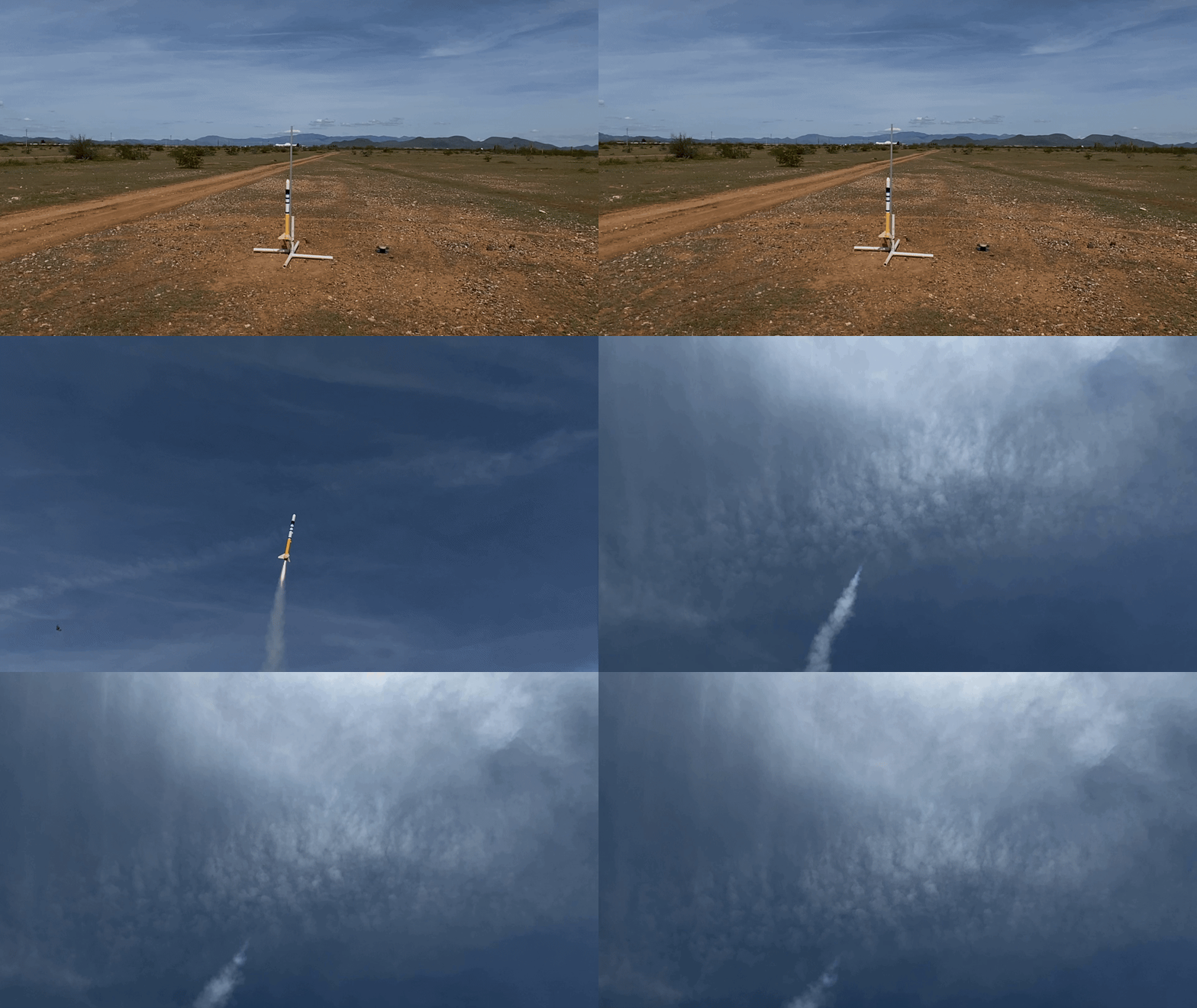
Introduction
In the realm of sport rocketry, particularly within competitive settings like TARC, the ability to consistently reach a target apogee is of paramount importance. Traditional methods of altitude adjustment often involve modifying the rocket's weight or motor selection, which can be imprecise and affected by environmental variables. To address this challenge, we explored the implementation of active airbrake systems that dynamically adjust the rocket's drag during flight, enabling real-time altitude control.
An airbrake system introduces a variable drag mechanism, increasing the aerodynamic resistance to reduce ascent velocity and limit maximum altitude. Designing such a system for mid-power rockets involves overcoming constraints related to weight, size, and energy consumption while ensuring reliability and effectiveness.
This paper details the conceptualization, design, and testing of two active airbrake prototypes and their associated electronic control units. We discuss the mechanical and electronic design considerations, the predictive algorithms used for deployment timing, and the results from flight tests that evaluate the systems' performance.
Design and Development
Constraints and Objectives
The primary objective was to develop an airbrake system capable of precise altitude control without exceeding the strict constraints of TARC competitions:
- Weight: Total system weight (airbrake and electronics) not exceeding 150 grams.
- Dimensions: Fit within a 2-inch (5.08 cm) diameter body tube with a maximum length of 10 inches (25.4 cm).
- Energy Efficiency: Minimize power consumption to ensure system reliability throughout the flight.
- Reliability: Consistent deployment under varying flight conditions.
Airbrake Designs
Airbrake Design 1
The initial design focused on increasing the rocket's surface area using deployable fins actuated by a linear actuator:
- Mechanism: Fins extend outward from the rocket's body to increase drag.
- Actuation: Linear actuator programmed to deploy at specific altitudes.
- Materials: 3D-printed frame and fins.
- Specifications:
- Voltage: 6 V
- Current: 550 mA
- Power: 3.3 W
- Dimensions: 55 mm × 55 mm × 100 mm
- Weight: 75 g
Performance and Challenges:
While effective in theory, this design encountered issues with inconsistent deployment due to aerodynamic forces resisting fin extension and occasional actuator malfunctions.
Airbrake Design 2
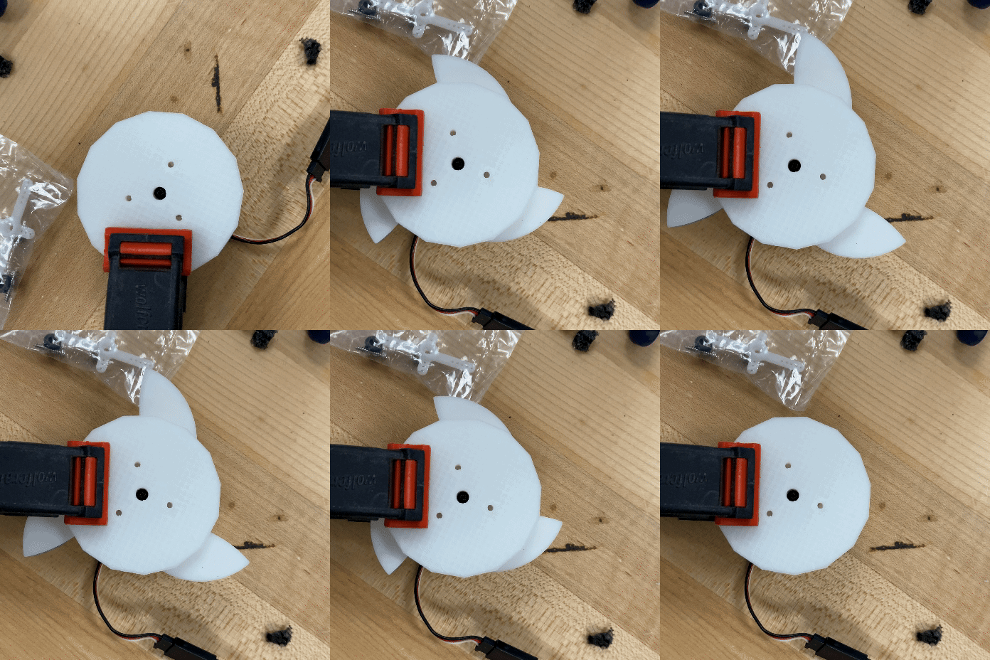
To address the limitations of the first design, a second iteration was developed utilizing a servo motor and gear mechanism:
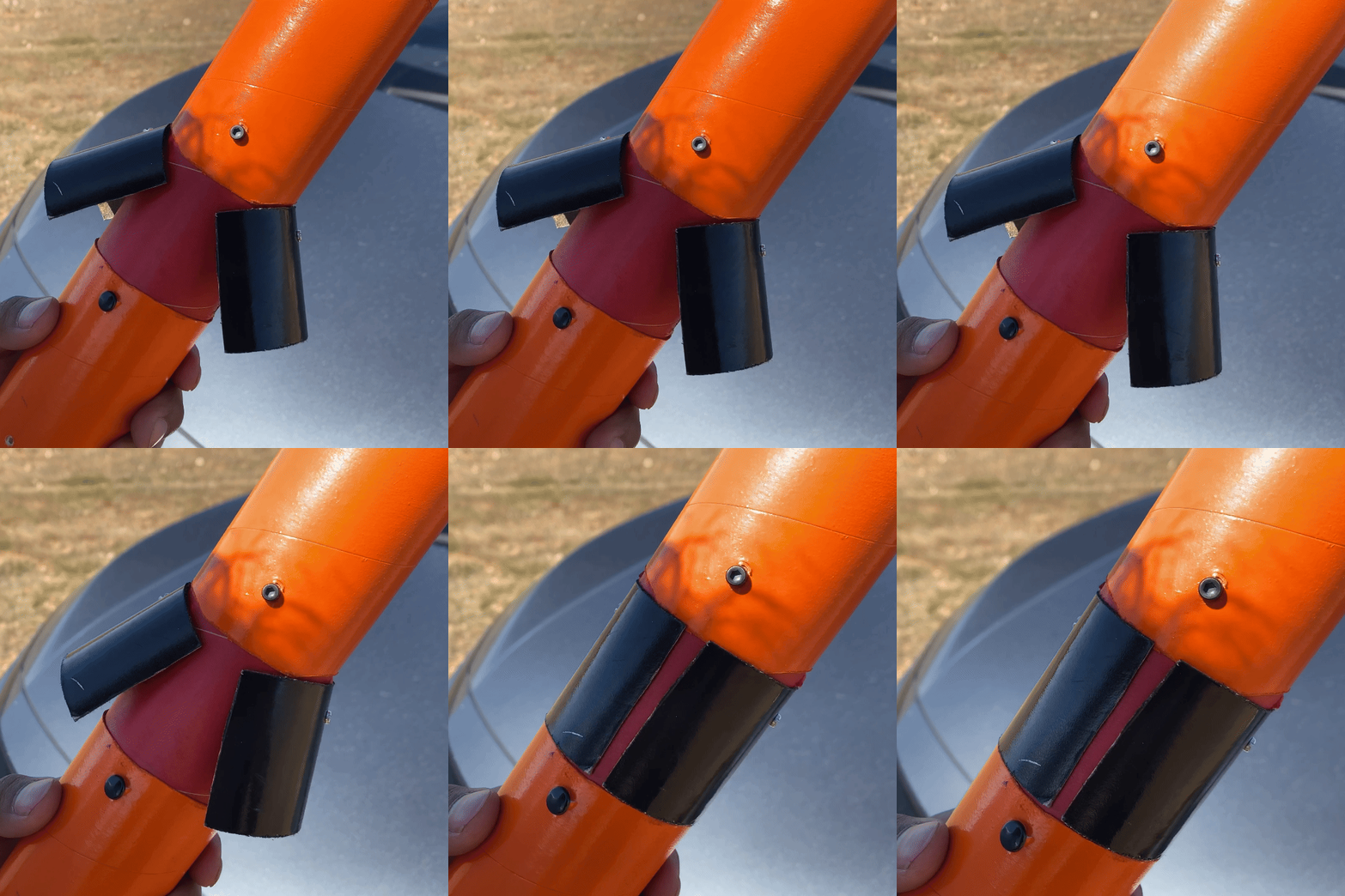
- Mechanism: "Petal" panels unfold outward from the rocket's body.
- Actuation: Servo motor provides rotational motion for reliable deployment.
- Improvements:
- Reduced mechanical resistance during deployment.
- Decreased system size and weight.
- Specifications:
- Voltage: 5 V
- Current: 250 mA
- Power: 1.25 W
- Dimensions: 55 mm × 55 mm × 50 mm
- Weight: 45 g
Performance:
This design achieved more consistent deployment due to its simplified mechanism and reduced susceptibility to aerodynamic forces.
Avionics Systems
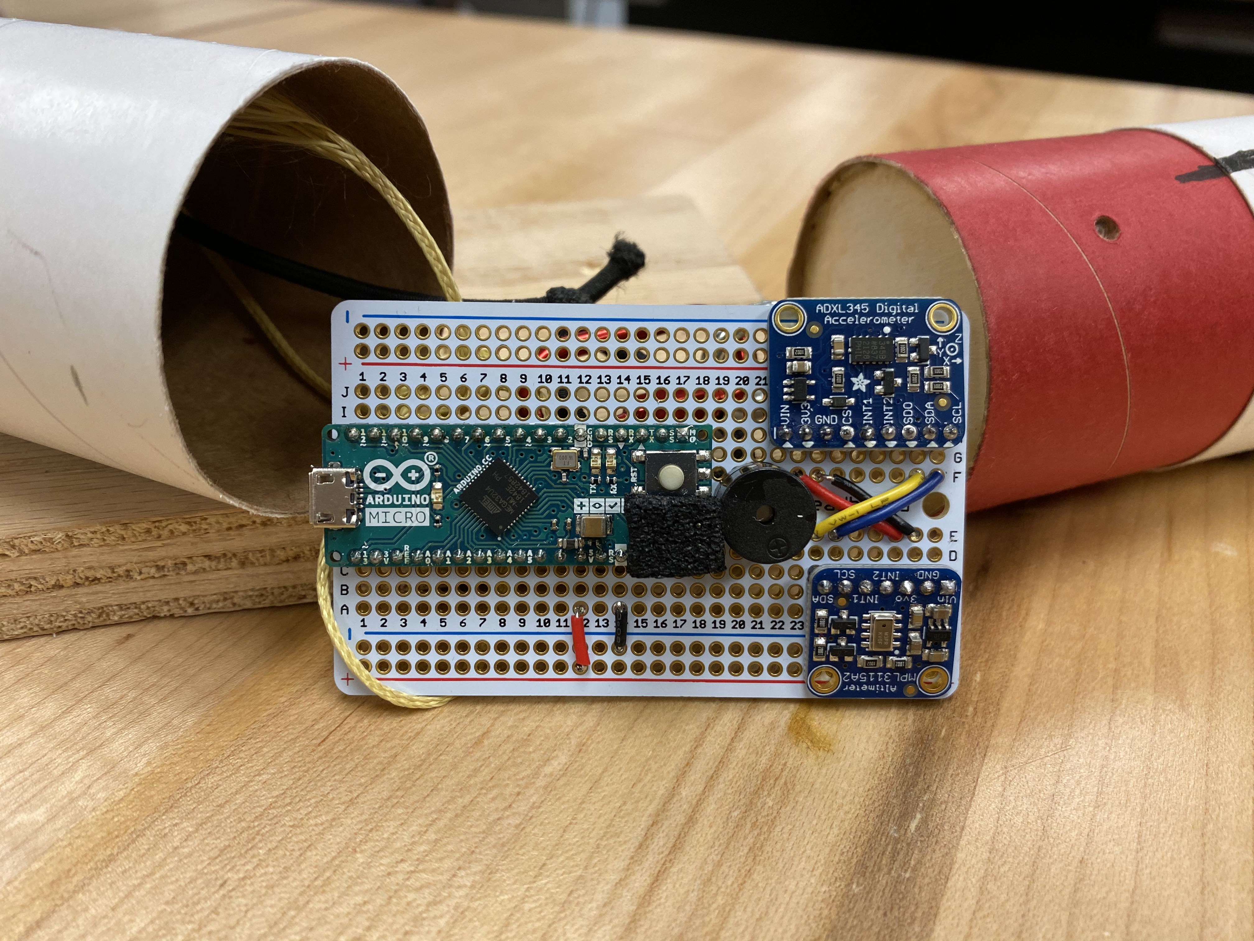
Avionics Design 1
An energy-efficient setup aimed at rockets requiring minimal altitude correction:
- Processor: Arduino Micro (ATmega32u4, 16 MHz)
- Sensors:
- Accelerometer: ADXL345
- Barometer: MPL3115A2
- Interfaces:
- Futaba J female connector
- SD card connector
- Power System: 500 mAh Li-Po battery boosted to 5 V
- Sampling Rate: Up to 2.5 Hz
- Dimensions: 132 mm × 52 mm × 40 mm
- Weight: 75 g
Avionics Design 2
A more accurate system for rockets needing significant altitude correction:
- Processor: Arduino Pro Mini (ATmega328, 16 MHz)
- Sensors:
- Accelerometer: ADXL345
- Barometer: BMP388
- Interfaces:
- Futaba J female connector
- SD card connector
- Three switches
- Power System: 1200 mAh Li-Po battery boosted to 5 V
- Sampling Rate: Around 50 Hz
- Dimensions: 95 mm × 52 mm × 40 mm
- Weight: 68 g
Enhancements:
- Higher sampling rates for improved data resolution.
- Increased processing capabilities to handle more complex algorithms.
Methodology
Altitude Prediction Algorithm
Due to limited onboard computing resources, we employed simplified kinematic equations to predict the rocket's apogee:
Where:
- : Predicted maximum altitude
- : Current altitude
- : Velocity (estimated)
- : Acceleration due to gravity (9.81 m/s²)
- : Drag coefficient
- : Cross-sectional area of the rocket
- : Air density
- : Mass of the rocket
Velocity Estimation:
Due to the absence of an airspeed sensor, velocity was calculated using:
- Differential Altitude:
- Integrated Acceleration:
- : Vertical acceleration from the accelerometer
- : Time interval between readings
Combined Velocity:
An average of and was used to improve accuracy.
Noise and Error Mitigation
Sensor noise and deviations were significant challenges:
- Barometer Noise: High susceptibility to pressure fluctuations.
- Accelerometer Deviations: Errors due to non-vertical flight paths.
Solutions:
- Implementing an error coefficient adjusted manually pre-flight.
- Considering advanced filters (e.g., Kalman filter) for future iterations.
- Modifying the drag coefficient (( C_d )) to calibrate predictions.
Structural Integrity Calculations
To ensure the airbrake could withstand deployment forces, we calculated the maximum safe deployment velocity:
- : Force exerted on the fins
- : Deployment angle (maximum 60°)
- Other variables as previously defined.
Wind Tunnel Testing
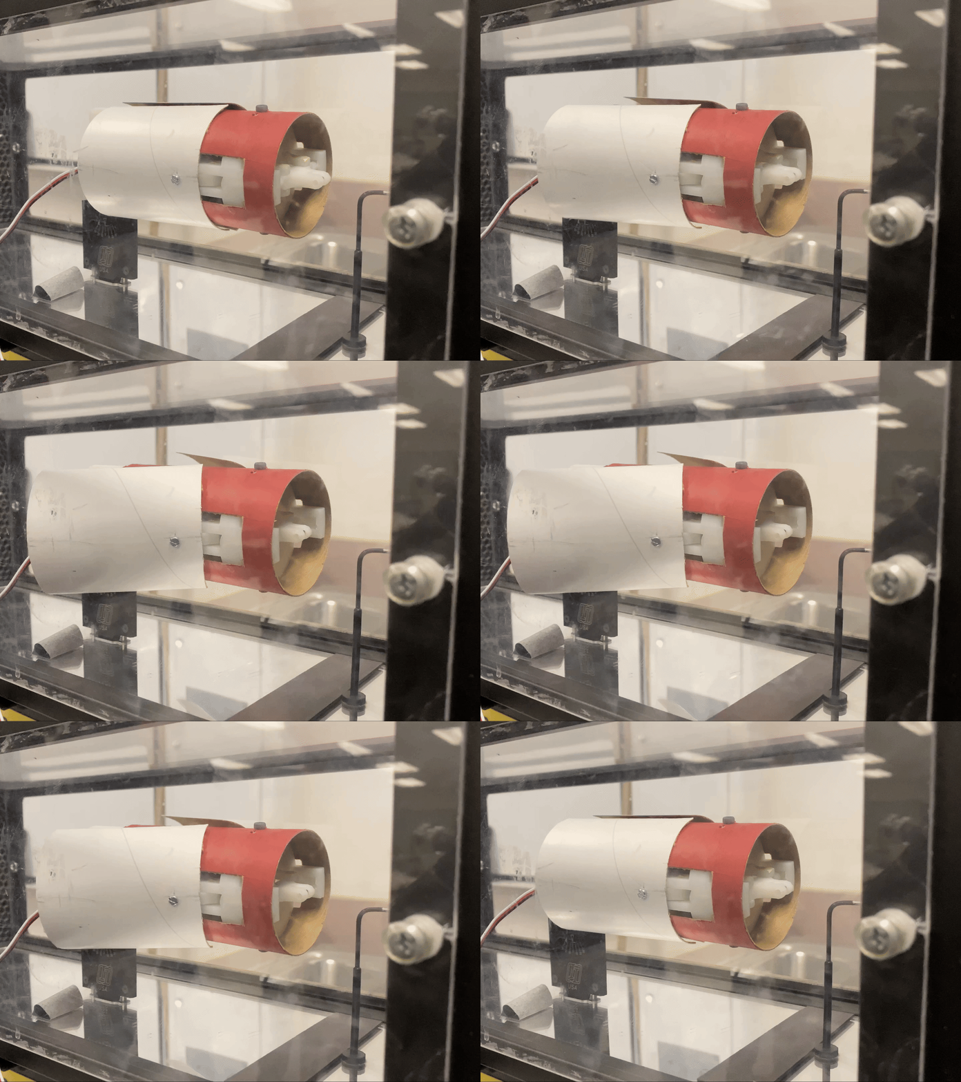
To further validate our calculations and assess the airbrake's performance, we conducted extensive wind tunnel testing:
- Drag Coefficient Measurement: We measured the drag coefficient (Cd) of the rocket with and without the airbrake deployed at various wind speeds.
- Efficiency Analysis: We calculated the airbrake's efficiency by comparing the increase in drag to the additional frontal area when deployed.
- Flow Visualization: Using smoke and high-speed cameras, we observed the airflow patterns around the deployed airbrake to identify any unexpected turbulence.
Results showed a 2x increase in drag coefficient when the airbrake was fully deployed, confirming its effectiveness in altering the rocket's aerodynamic properties.
Structural Testing
To ensure the airbrake's durability under flight conditions, we performed thorough structural testing:
- Static Load Tests: We applied increasing loads to the deployed airbrake fins until failure, determining their maximum load capacity.
- Fatigue Testing: We subjected the airbrake mechanism to repeated deployment cycles to simulate multiple flights and assess long-term reliability.
- Vibration Testing: Using a shake table, we exposed the entire airbrake assembly to flight-like vibrations to ensure all components remained secure.
These tests confirmed that the airbrake could withstand forces up to 1.5 times the maximum expected during flight, providing an additional safety factor beyond our initial calculations.
Findings
Our structural integrity calculations and testing revealed that Design 1 could safely deploy at velocities up to 133 m/s (298 mph). This provided a comfortable safety margin, as test flights recorded maximum velocities of 120 m/s (268 mph). Based on these findings, we concluded that the airbrake system possessed sufficient structural integrity to withstand deployment forces at any point during the flight trajectory.
Implementation
Software Architecture
The Arduino-based control software comprised several key components:
- Initialization: Sensor calibration, GPIO setup, and pre-flight checks.
- Main Loop:
- Data Acquisition: Collecting altitude and acceleration data.
- Velocity Calculation: Estimating current velocity.
- Apogee Prediction: Using the simplified formula to predict maximum altitude.
- Deployment Decision: Triggering the airbrake if predictions exceeded target altitude.
- Data Logging: Storing sensor readings and calculated values to the SD card.
- Functions:
- LED Indicators: Providing visual status updates.
- Buzzer Alerts: Signaling critical events or errors.
- Actuator Control: Managing servo or actuator movements.
Mechanical Integration
- Airbrake Installation: Ensured seamless integration with the rocket's airframe.
- Testing: Ground tests to verify mechanical reliability and deployment speed.
- Adjustments: Modifications made based on test outcomes to improve performance.
Results
Flight Test Analysis
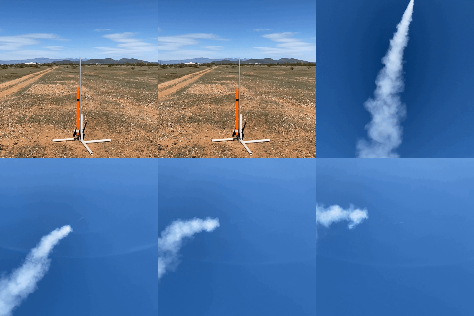
Flight #8
- Objective: Test Airbrake Design 1 and Electronics Design 1.
- Motor: Aerotech F42-4T
- Target Apogee: 243.84 m
- Actual Apogee: 223.81 m
- Predicted Apogee (Post-Flight): 223.72 m
- Deviation from Target: 20.03 m (8.21%)
- Prediction Accuracy: 0.09 m (0.04%)
- Data Rate: 2.5 Hz (125 data points)
Observations:
- High prediction accuracy when calculated post-flight.
- Lack of noticeable airbrake deployment effect in altitude data.
- Identified issues with deployment reliability.
Flight #15
- Objective: Evaluate Airbrake Design 2 with improved electronics.
- Motor: Aerotech F67-6W
- Actual Apogee: 243.38 m
- Predicted Apogee: 253.65 m
- Deviation from Target: 0.46 m (0.20%)
- Prediction Deviation: 10.27 m (4.22%)
- Data Rate: 25 Hz (850 data points)
Observations:
- Successful airbrake deployment confirmed by altitude graph anomalies.
- Noted sudden altitude spikes due to pressure changes affecting the barometer.
- Data corruption issues due to limited memory, later resolved by optimizing data strings.
Flight #22
- Objective: Achieve maximum precision in target altitude and flight time.
- Motor: Aerotech F67-6W
- Actual Apogee: 255.71 m
- Predicted Apogee: 261.21 m
- Deviation from Target: 11.87 m (4.87%)
- Prediction Deviation: 5.5 m (2.15%)
- Data Rate: 25 Hz (967 data points)
Observations:
- Drilled ventilation holes to mitigate pressure anomalies.
- Persistent inconsistencies in barometer data post airbrake deployment.
- Identified "ballooning" effect causing pressure fluctuations.
- Demonstrated improved data collection and airbrake effectiveness.
Data Interpretation
- Prediction Algorithm: Showed high accuracy when sensor data was reliable.
- Airbrake Impact: Confirmed ability to alter flight profile effectively.
- Sensor Challenges: Highlighted need for better pressure management and data filtering.
Discussion
The development of active airbrake systems proved feasible within the constraints of mid-power rockets. Key takeaways include:
- Design Evolution: Transitioning from a linear actuator to a servo mechanism improved reliability and reduced power consumption.
- Electronics Upgrade: Higher sampling rates and better sensors enhanced data quality, though at the cost of increased complexity.
- Algorithm Limitations: Simplified models were adequate but could benefit from advanced processing techniques.
- Mechanical Considerations: Aerodynamic forces significantly impact deployment; designs must account for these to ensure consistent operation.
Challenges:
- Sensor Noise: Affected the accuracy of real-time predictions.
- Data Management: Limited memory required efficient data handling strategies.
- Pressure Effects: Internal pressure changes necessitated structural adjustments.
Conclusion
The project successfully demonstrated the integration of small, energy-efficient active airbrake systems for precise altitude control in mid-power rockets. Despite facing challenges related to sensor accuracy and mechanical reliability, the systems achieved notable improvements in reaching target altitudes. The iterative design process highlighted the importance of addressing aerodynamic forces and optimizing electronic systems within the constraints of amateur rocketry.
Future Work
- Advanced Sensors: Incorporate more accurate barometric sensors or alternative methods for altitude measurement.
- Filtering Techniques: Implement real-time data filtering (e.g., Kalman filters) to improve prediction accuracy.
- Processor Upgrade: Use more powerful microcontrollers to handle complex algorithms and higher data rates.
- Mechanical Refinement: Further optimize airbrake designs to reduce aerodynamic disturbances and pressure anomalies.
- Comprehensive Testing: Conduct additional flights under varied conditions to validate system robustness.
Appendix
Technical Specifications
Airbrake Design Comparison
| Specification | Design 1 | Design 2 |
|---|---|---|
| Actuation Mechanism | Linear actuator | Servo motor with gears |
| Deployment Angle | Up to 60° | Up to 90° (petal design) |
| Surface Area | Larger fins | Smaller, more reliable panels |
| Voltage | 6 V | 5 V |
| Current | 550 mA | 250 mA |
| Power Consumption | 3.3 W | 1.25 W |
| Dimensions | 55 mm × 55 mm × 100 mm | 55 mm × 55 mm × 50 mm |
| Weight | 75 g | 45 g |
Electronics Design Comparison
| Specification | Design 1 | Design 2 |
|---|---|---|
| Processor | Arduino Micro (ATmega32u4) | Arduino Pro Mini (ATmega328) |
| Clock Speed | 16 MHz | 16 MHz |
| Memory | 32 KB Flash, 2.5 KB SRAM | 32 KB Flash, 2 KB SRAM |
| Sensors | ADXL345, MPL3115A2 | ADXL345, BMP388 |
| Sampling Rate | Up to 2.5 Hz | Around 50 Hz |
| Power Supply | 500 mAh Li-Po, boosted to 5 V | 1200 mAh Li-Po, boosted to 5 V |
| Dimensions | 132 mm × 52 mm × 40 mm | 95 mm × 52 mm × 40 mm |
| Weight | 75 g | 68 g |
Code Overview
- Libraries Used:
- Sensor interfaces (e.g.,
Adafruit_BMP388.h,Adafruit_ADXL345_U.h) - SD card (
SD.h) and SPI (SPI.h) communication - Servo control (
Servo.h) - Key Functions:
- Initialization: Sets up hardware components and performs sensor calibration.
- Data Acquisition: Reads sensor data at specified intervals.
- Prediction Algorithm: Calculates estimated apogee.
- Deployment Logic: Determines when to deploy the airbrake.
- Data Logging: Writes sensor data and calculated values to SD card.
- Feedback Mechanisms: Controls LEDs and buzzer for status indication.
Flight Data Samples
- Graphical Analysis: Altitude vs. time graphs showed expected flight profiles with noticeable changes upon airbrake deployment.
- Data Integrity: Improved in later flights due to higher sampling rates and optimized data handling.
Acknowledgments
We extend our gratitude to our mentors, teachers, and the TARC organizers for their support and guidance throughout this project. Their contributions were invaluable to our learning and the success of this endeavor.
Due to project disruptions caused by the COVID-19 pandemic, the development was halted during the final prototyping stage. Further testing and refinements are required to fully realize the system's capabilities.
